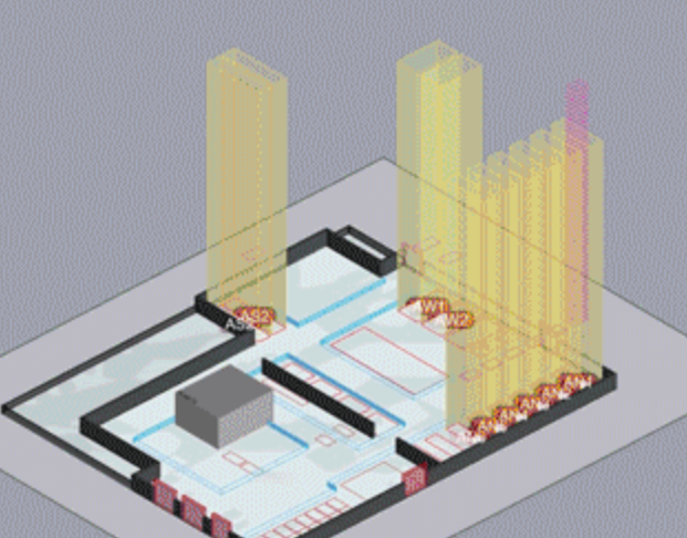
As we were brainstorming for this project, we considered several precedent designs. One major inspiration was Traversina I, a bridge across a Swiss ravine supported underneath by triangular wooden structures sitting on metal cables. We knew we wanted to use string/floss as a member bearing tension, so this was a good starting-off place as a structure that is both simple and beautiful. Per Renaud’s advice, we also looked into constructing a space truss, and used a few images of space-truss roofs for inspiration. This precedent had a much stronger influence on our final design.
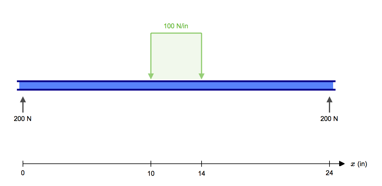
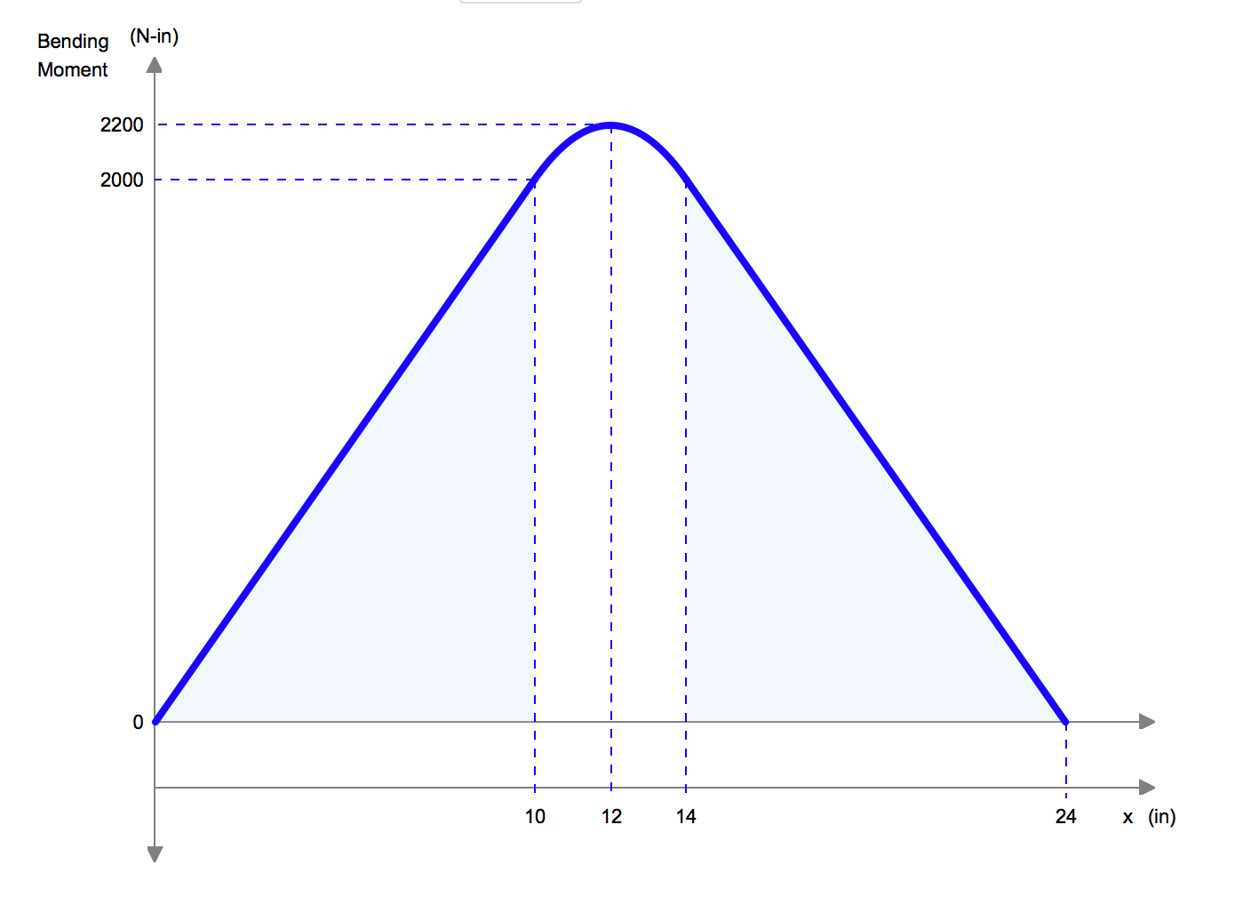
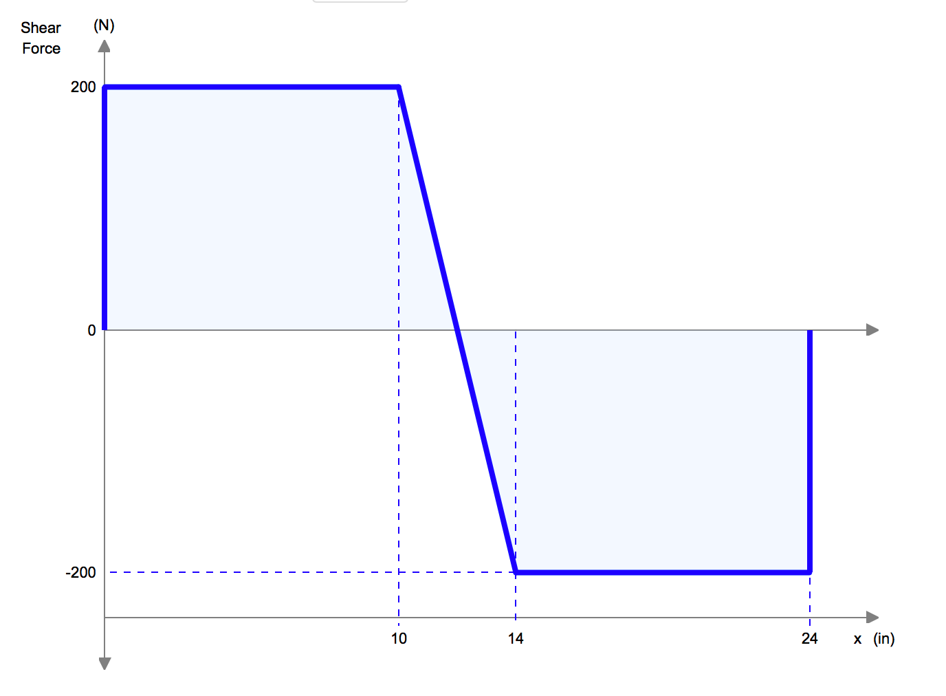
When designing our beam, we also spent some time looking at the standard graphs of a simple straight beam, as can be seen below. From this quick analysis, and from looking at the moment diagram, it gave us some intuition into the structural design and geometry of the beam.
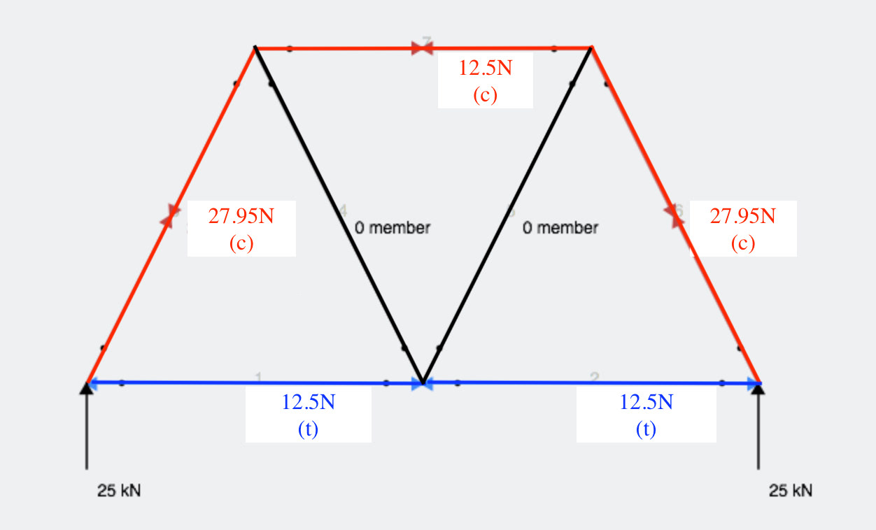
We based our calculations off of the bottom member breaking, as informed by our truss analysis.
Based on intuition and previous examples of trusses from class, we assumed that the top member would be in compression and the bottom would be in tension. This was part of the initial rationale for using floss as the bottom member, but working out how to attach the internal members to the floss proved much more difficult than we’d anticipated. We decided to stick with balsa wood on the bottom, reinforcing it with floss at the end of construction.
Truss analysis of the central piece (see diagram at right) confirmed our assumptions about the top and bottom members’ internal forces. Our rough calculations gave a value of 12.5 pounds for the axial force in each section of the bottom member, so we based our sizing of this member off of this maximum value (i.e. if there were no other members in the truss). Because we were initially using balsa wood that was ¼ in on either side, we oversized this member slightly to ½ by ¼. This was motivated by the knowledge that the joints would likely be a weakening factor in the beam’s construction. However, sizing the beam based on buckling calculations is erroneous because buckling occurs in compression, not tension. Further analysis (see attached) indicates that the limiting piece was actually the top member, which should have been sized to account for buckling/crushing. We can say retroactively that the top member’s cross-section should have been sized at approximately 0.3” on each side, which was actually very close to the real thing.
The top member, extending across the tips of the space trusses, is in compression when the beam is loaded. We hoped that the floss (and the tension in the balsa members on the bottom) would pull the ends of the top member down, initially strengthening the beam as the truss was further loaded.
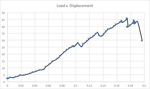
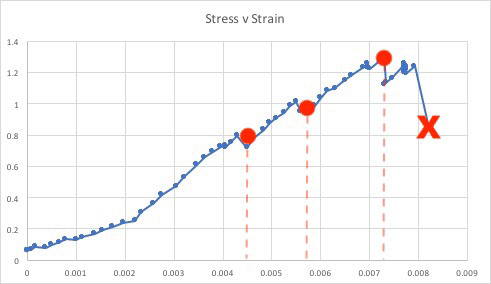
The graphs below depict the Load v. Displacement curve, and the Shear Stress v. Strain Curve.
When determining the Stress values for the second graph, we used the Shear-Stress Equation =F/Awhere F is the Force applied and A is the (average) cross-sectional area of our beam with area parallel to the applied force vector. While we have not studied this equation, we wanted to attempt to produce a stress-strain graph for the report.
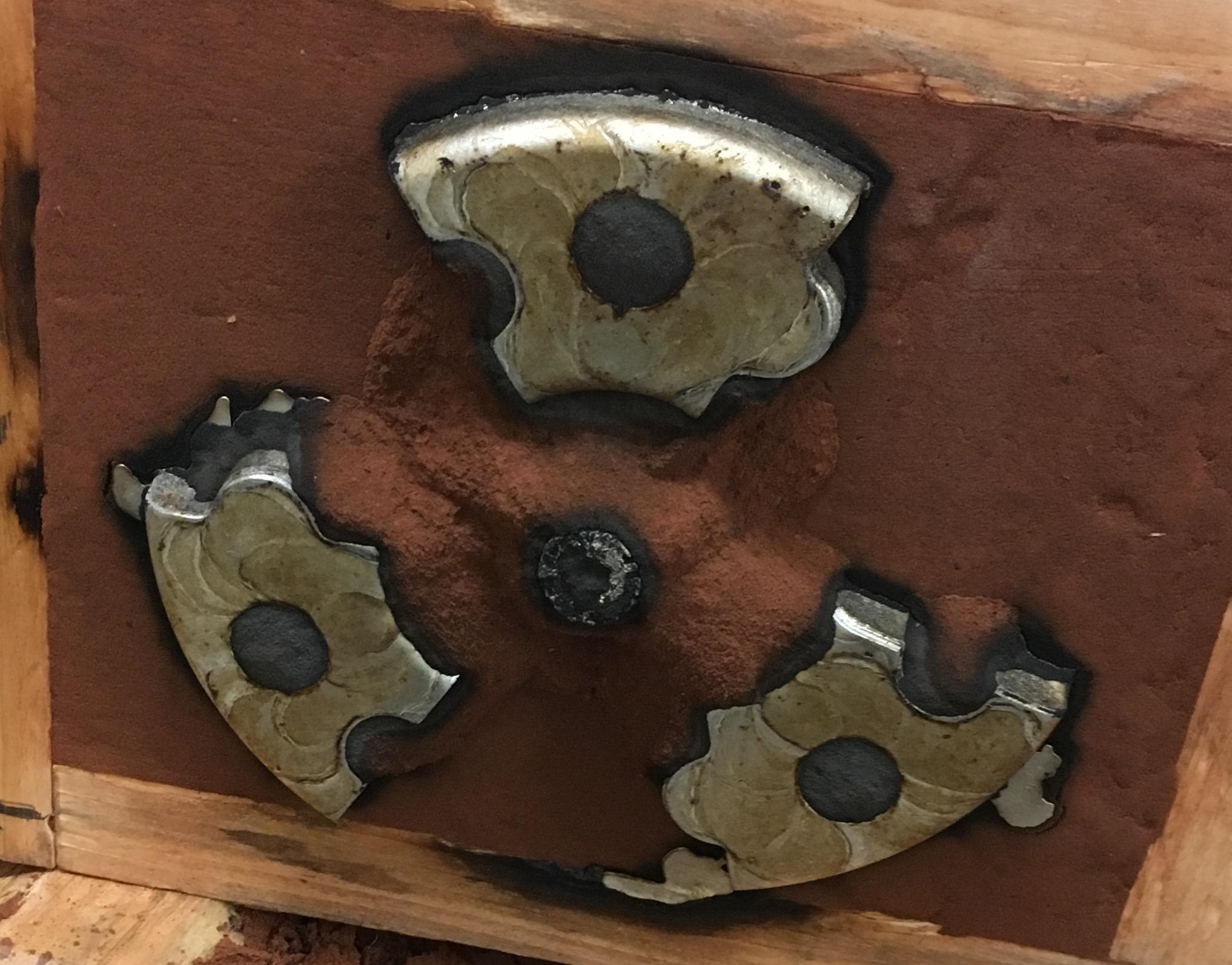
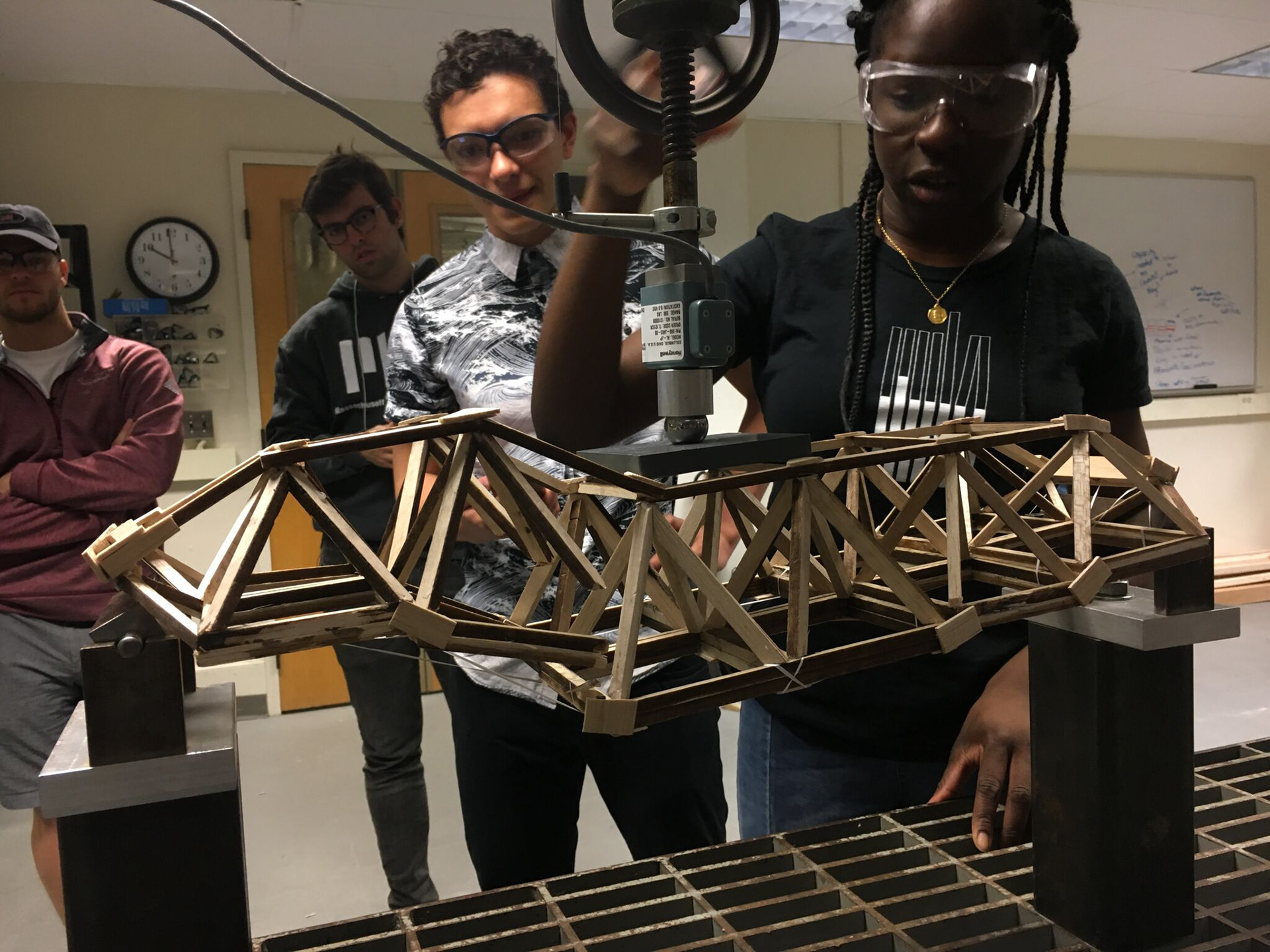
As can be seen on the graph when load was first applied, the beam became stiffer. It was not until about 26lbs where there was a slight dip in the slope. As the structure did not completely fail here, and also having heard a loud snapping noise in the lab at the time, we perceived this to be the elastic limit and perhaps there was local buckling, but in actuality the snapping noise was the failure of one of our many space truss joints (as can be seen in the image below). Nevertheless as can be seen on the graph, even with this snapping setback, the structure continued to stiffen to about 36lbs. At this point there is a more significant change in slope, and we therefore deduced this to be the Elastic Limit, which is the maximum extent to which our structure could be compressed/bent before permanent deformation/reshaping. Shown graphically, the structure reached a maximum load of just of just under 50lbs. At this point we were able to see significant global buckling of the structure which in a way dramatized the subtle curvilinear profile of our design (pictured below). From here on necking occurred until the structure reached its fracture capacity.
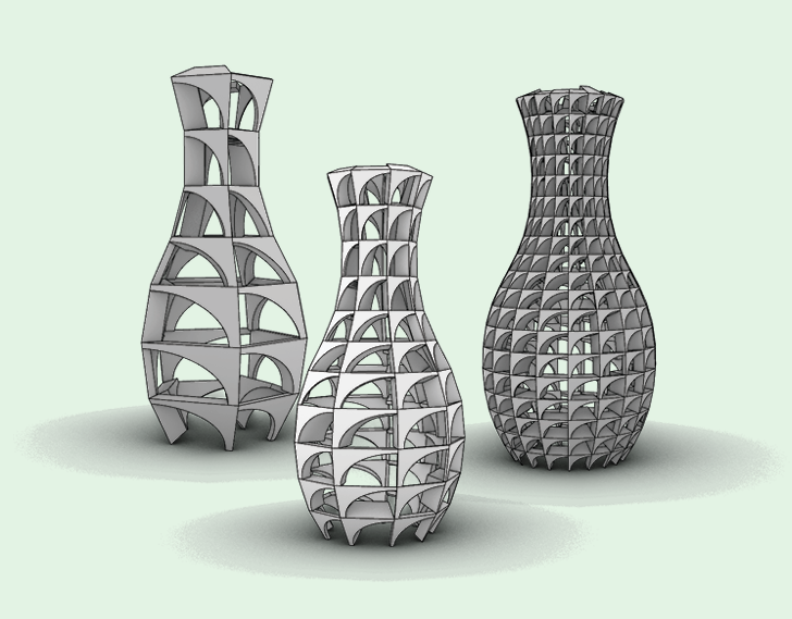
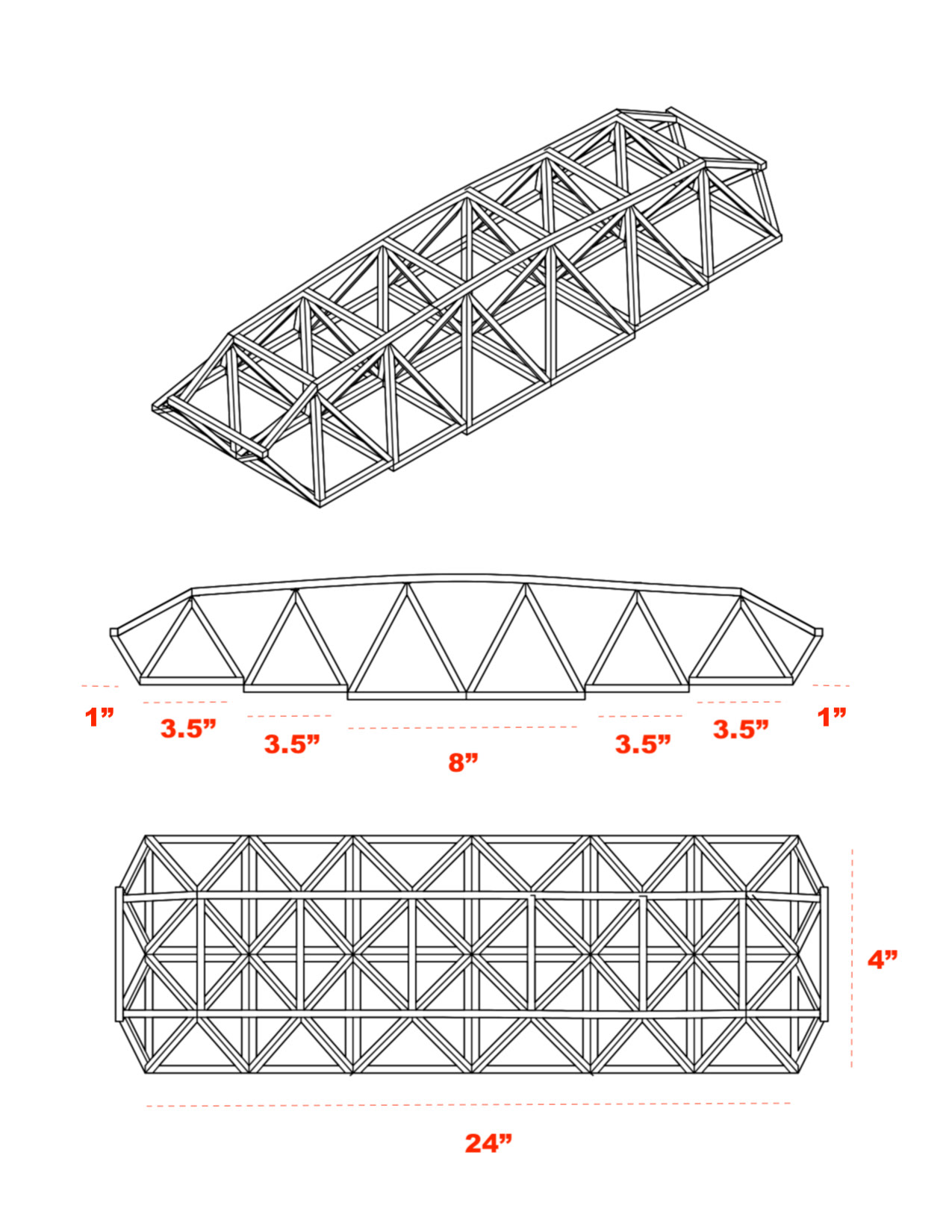
From the beginning of the project, we knew we wanted to design something visually pleasing, but still effective and structurally stable. It was therefore unsurprising that many of our initial designs involved trusses. Approximating the curvilinear form of our beam was something we still are very proud we did, and the accent of floss is also something we are happy about pursuing because it gave us some insight into the uses of cables in actual bridges.
Nevertheless, there are a few areas of both our design and construction that we would change. For one, we would certainly pay better attention to the supports that our beam had to rest on, as we had to force our structure (which turned out to be too long) between the posts, compressing the bottom members and deforming the beam before the load was even applied. In a way, we inadvertently created a statically indeterminate structure. In fact, the final bent form the beam took is a direct result of its being crammed between the two posts: its overall horizontal length was shortened by making one of the sections more diagonal.
The joint connections are also another area we would take more time designing. We were warned that too many connections at a single point would be hazardous to the structural integrity of our beam; however, due to the geometry of the space trusses and our design, having 4 members meeting at a single point was to some extent unavoidable. However, if we were to do another iteration, we would certainly think of more creative and effective joint connections, especially with better use of gusset plates that would increase the contact surface area between multiple members.
One fundamental issue with the design and construction that we anticipated was that our design would be a mere approximation of a curvilinear geometry. While there would always be an imbalance between the desired design curvature and the plausible geometry of the beam, perhaps more explorations in bending balsa wood would have better beneficial (similar to the top bent top member). One particular problem that resulted directly from this fundamental issue was the problem of the joints between the bottom members. Were we to do this project again, we would design them slightly differently (see diagrams in calculations) to avoid making their joints so weak.